Detailed Engineering of
Grain Elevators
From initial complex conceptualization to facility commissioning. We deliver detailed engineering for large-scale processing plants and produce high-fidelity BIM models.
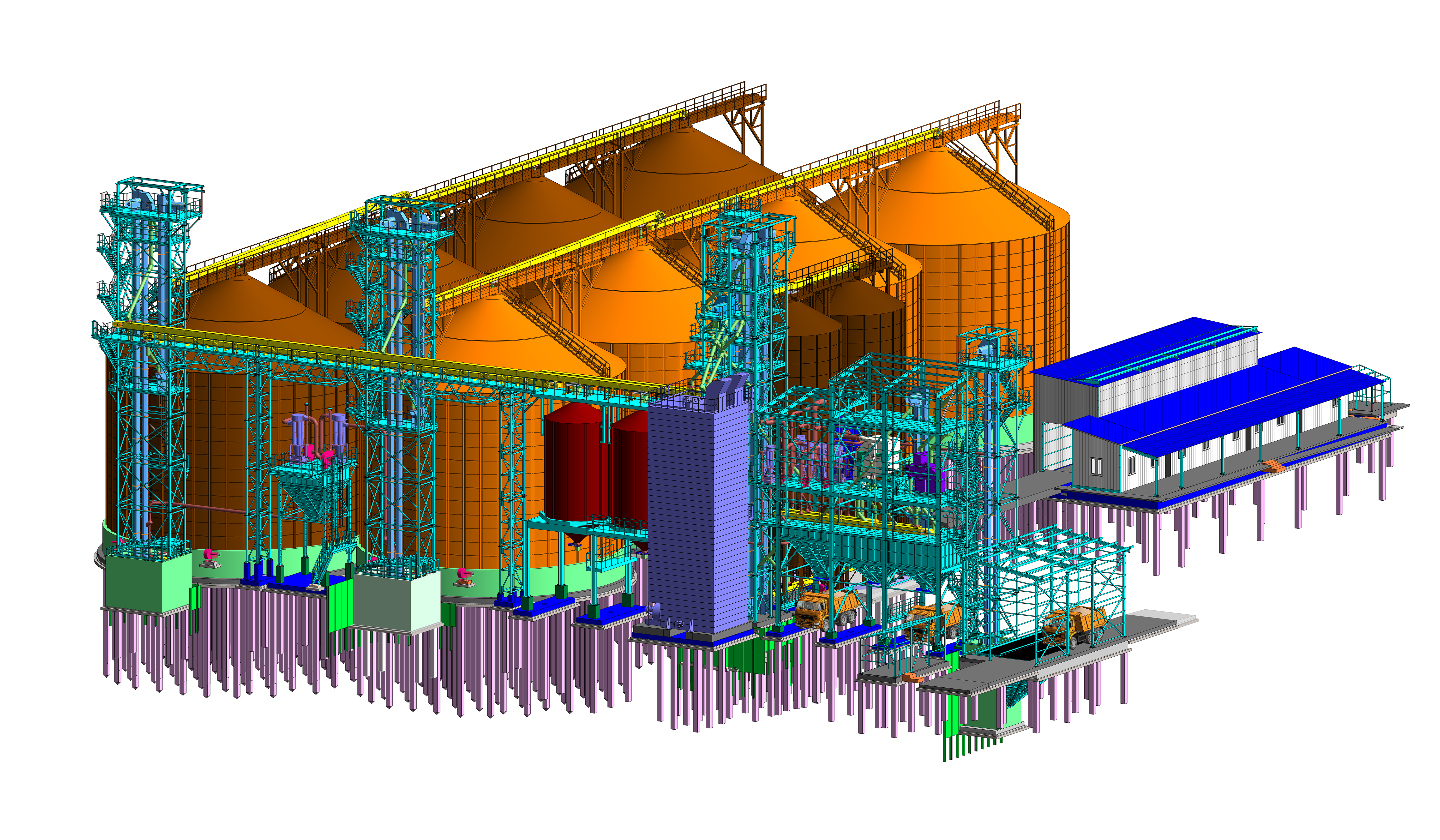
Grain Handling and Storage Facility Engineering
A grain elevator is an efficient solution for your business. A modern, high-tech elevator complex can receive, process, and preserve your harvest. Grain prices are traditionally lowest during harvest season and highest in spring. Storage needs vary significantly among businesses. Some require multiple cycles of filling and emptying their silos, while others need single-time filling after harvesting their own crop or storage of purchased grain for further processing or sale. Owning storage capacity enables you to preserve large volumes of high-quality grain.
We will engineer the equipment layout for each process area
Scope of Engineered Facilities
Core project portfolio
- Weighbridge complex
- Laboratory with sampler unit
- Truck raw material receiving bay
- Rail raw material receiving bay
- Receiving and cleaning tower with scale
- Metal silo storage for grain
- Control room and electrical switchgear room
- Drying unit
- Truck loading bay
- Administrative and amenities building
Auxiliary facilities
- Fire water reserve tank with pump station
- Water treatment plant
- Gas supply system
- Transformer substation
- Electricity
- Water
- Natural gas
- Grains and oilseeds
- Commercial grain
Stages of
Grain Elevator Engineering
We develop design and working documentation in BIM, performing all relevant calculations of the strength of the complex structures, which allows us to save the customer a significant part of the financial costs for concrete work, the manufacture of metal structures and the selection of process equipment, while eliminating all collisions between elements at the design stage, which is one of the most important tasks in the design of agricultural facilities.


Request a quote for your project

- Client needs assessment
- Preliminary design brief
- Production goals and objectives

- Expected deliverables
- Project timeline
- Engineering service cost

- Conceptual 3D model development
- Site integration of the complex
- Contract documentation

- Geodetic surveys
- Geotechnical surveys
- Environmental surveys

- Equipment modeling
- Structural modeling
- Clash detection and resolution

- Load analysis
- Structural analysis
- Bill of materials and equipment specifications

- Preparation of the submission package for state or non-state review
- Resolution of all expert comments
- Securing the positive review report for construction permit

- Detailed structural geometry modeling
- Component connection design development
- Material property data integration

- Detailed plans and sections
- Utility networks coordination
- Comprehensive material and equipment schedules
Comprehensive BIM-based
facility design
ATI develops projects using BIM technology. The key advantages of BIM models are their precision, high level of detail, superior visualization capabilities, and significant reduction in construction timelines. Projects based on quality BIM models exhibit 30% fewer errors compared to those utilizing CAD.
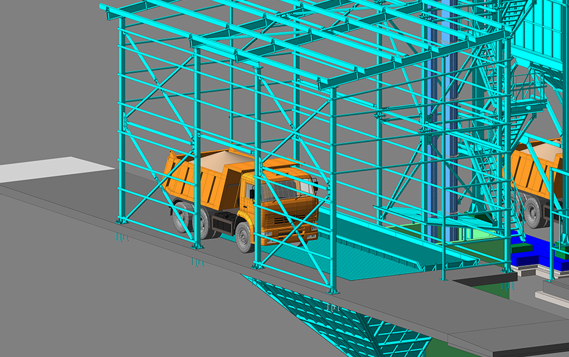
Precise and detailed BIM models for clash avoidance

in project documentation
for display
and drag the image

BIM models provide precise geometry, dimensions, and spatial positioning of all components. Conventional design typically approximates utility routing without detailed node design or thorough tracing, forcing construction teams to improvise assembly methods. BIM-driven design eliminates uncoordinated nodes, sections of engineering networks, and all clashes or discrepancies.
During the design phase, it is possible to verify whether sufficient space is allocated for each utility to accommodate technological processes and to confirm that pipes and cables do not intersect. This approach minimizes the risk of installation errors.
Stages of 3D model development


Completed projects based on our designs


Client benefits when partnering with
ATI engineering

Facility conceptual model

The facility conceptual model is developed using BIM technologies to provide an initial project representation and align basic design solutions with the client. We develop preliminary solutions based on client requirements and technological needs for buildings and structures. The conceptual model constitutes a distinct stage of pre-project development.
Detailed design development

An information model is developed in BIM across all disciplines at LOD 100 and 200. Upon model completion, a full set of documentation is issued, sufficient for expert review and construction permit acquisition. Working in BIM enables the delivery of high-quality design documentation already at the detailed design stage, free of clashes and with fully coordinated disciplines. Technical solutions developed in BIM are justified and optimized.
Construction Documentation development

Master plan development

Structural engineering solutions

Utility networks and equipment

Process engineering solutions

Specialized and additional design documentation sections

All specialized sections of the design documentation are developed to the extent required for expert review approval.
These include civil defense measures and emergency prevention plans for natural and man-made disasters, developed for hazardous production facilities, especially hazardous, technically complex, and unique structures, as well as defense and security site facilities.
Supervision by the engineer's Supervision

The availability of a BIM model and detailed construction documentation enables high-quality, thorough, and responsible designer`s supervision during the construction, reconstruction, and major renovation of buildings and structures. The supervision provided by the design organization is carried out in coordination with specialists performing construction control.
We operate across Russia, CIS countries, and globally


We perform pre-contract feasibility studies and preliminary design


FAQ
The cost of engineering depends on the scope and complexity of the facility's components. The number of structures to be designed directly impacts the price. The quantity and complexity of the design disciplines required are also significant factors. The greater the variety of utility networks within the facility, the higher the engineering cost.
New construction is typically less expensive than reconstruction. In reconstruction projects, all existing building elements must be modeled and checked for new loads, followed by equipment layout, development of strengthening solutions, and potential process redesign due to spatial constraints or the high cost of reinforcing existing structures. The search for optimal solutions, equipment replacement, and the time invested all contribute to higher design costs.
The design of a grain elevator typically requires 80 to 120 working days:
- 20–30 working days for 3D model development
- 20–30 working days for detailed design development
- 20–30 working days for non-state expert review
- 20–30 working days for construction documentation development
The requirement for a state expert review will extend the schedule by approximately 60 working days, covering the period from document preparation to receiving a positive approval.
Reconstruction projects typically take longer to design than new complexes.
If equipment suppliers are changed during the design process, this necessitates modifications to the 3D model and impacts all related structures—steel and reinforced concrete floors, foundations, and gravity flow systems—as they are custom-designed for each specific equipment unit. The client must understand this and approach supplier selection with utmost seriousness. Implementing structural changes during the design phase is a time-consuming process.
Data on subsoil conditions is essential prior to commencing design. This necessitates preliminary site investigations. If geotechnical surveys for the project site already exist, design can begin immediately. If not, conducting these investigations typically requires 20-40 working days. It is important to note that after the final 3D model is created and the exact facility location is determined, additional targeted site investigations at specific points will be required.
- Title documents for the land plot
- Urban development plan
- Site investigation reports
- Approved list of process equipment to be used
- Technical specifications from the equipment supplier
In most cases, structural analysis is performed using the LIRA-SAPR software suite. However, certain tasks exist for which software packages cannot provide precise or reliable results. In such instances, we perform manual calculations. Regardless of the calculation method employed, we guarantee the reliability of the results.
The non-state expert review and development of construction documentation typically require 60-100 working days. However, construction may need to start earlier due to weather conditions or urgent project commissioning requirements. We can prepare documentation for early construction start prior to completing the expert review and obtaining the construction permit. While we guarantee successful completion of the non-state expert review, all risks associated with commencing construction without permits are borne by the client.
Upon completion of the design stages "Detailed Design" and "Construction Documentation," the client receives the documentation in PDF format. Following the client's review of all documents, incorporation of required adjustments, and final payment, we print and bind four hard copies of the complete documentation and ship them to the client within 20 working days. Provision of drawings in DWG format is available upon request.